LESARD: Subdomain’s definition module
The module FluidSubdomains takes care of the initial subdomains’ definition.
Depending on the parameters given in the Problem’s module, it creates the spatial
patches over the computational domain (aka. the mesh).
Page navigation
Features
The module furnishes the functions that initialise automatically the initial fluid subdomains according to the parameters given by the user in the problem’s definition. The available routines can be categorized into three main categories:
Generic subdomains definition routines (the only functions to consider when being a simple user)
Domain splitting routines (the technical unitary part of the generic subdomains definition routine, e.g. cut a plane through Bezier lines, define droplets)
Flagging degrees of freedom and vertices according to the freshly defined sudomains
Note
Any is non fully disconnected domain is supported, even non arc-connected ones. However, it may fail if the given domain includes degenerated boundaries (i.e. two overlapping boundaries, self-intersecting shapes etc)
Plotting the initial subdomains can be done with the routine
PlotSubdomainsincluded in theLSRD.SourceCode.PostProcessing.Plots_Matplotlibmodule.
Set-up
The only set-up is to load the relevant module (if not working with the full code, adapt the path to the FluidSubdomains module).
import ProblemDefinition.FluidSubdomains as SD
Generic principle and example of use
Principle
Given a mesh and a list of \(n\) shapes parametered in the format accepted by the routine LSRD.SourceCode.ProblemDefinition.FluidSubdomains.Mapper,
the main routine of the module (FluidSubdomains.GetSubdomains) defines \(n+1\) subdomains.
The domain of the first fluid will be set as the difference from the computational domain by the union of all the patches, while the subdomain of each following
fluid is created by patching each given shape of the list on the top of each other.
By example, if one defines three ordered fluids over a square domain correspoding to [“water”, “oil”, “milk”] and furnishes two patches corresponding to [“centred circle”, “half left plane”], then the milk will be set on the half left plane, the oil on the half right part of the centred circle and the water everywhere elsewhere (see more concrete examples below in the three fluids paragraph).
Note
It is also possible to only define a simple fluid. The furnished vector patch should then be empty.
Warning
When cutting the plane through a bezier or an arbitrary line, make sure that the line is cutting the domain completely (i.e that both extremities of the lines are beyond the domain’s outer boundary)
If during the process a subdomain appears to be empty, the code will abort due to inconsistency of the problem’s definition, for safety.
Examples
Various examples emphasising the definition of subdomains depending on their possible types are provided below,
and can be tested from the furnished example meshes. For a complete description of the parameters and possibilities,
see the documentation of LSRD.SourceCode.ProblemDefinition.FluidSubdomains.Mapper.
For the sake of the demonstration, we consider a L-shaped sample mesh having a hole in its middle and assume it has been preloaded in the variable
Mesh by e.g. the command
import Meshing
Mesh = Meshing.Meshing_DualMesh.DualMesh(MeshName, MeshOrder, MeshType, 20).Mesh
Case of two fluids
We first explain the principles of domain splitting and patching on a simple two fluids definition. One first possibility is to create “bubbles” by specifying as a parameter (4, BoxCenterX, BoxCenterY, BoxWidthX, BoxWidthY, BubblesDiameter, BubblesSpacingX, BubblesSpacingY) where the box is the rectangular area within which the bubbles should be created. Note that (as in the right figure case), if the radius of the bubble is larger than the given spacing, the bubbles will be merged accordingly.
Generate disconnected bubbles
patch = [(4, 0.5, 1.0, 0.8, 0.8, 0.05, 0.15, 0.15)]
SD.GetSubdomains(patch, Mesh)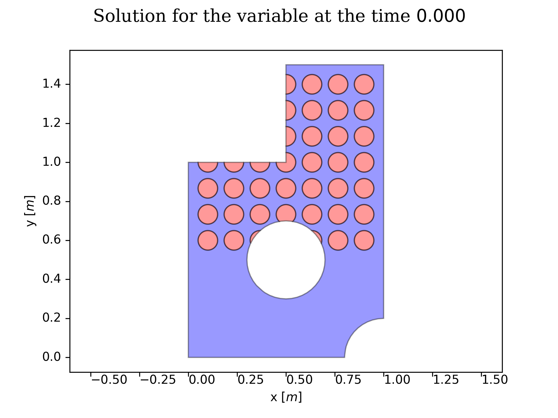
Generate partially merged bubbles
patch = [(4,0.5, 1.0, 1.8, 0.8, 0.05, 0.15, 0.15)]
SD.GetSubdomains(patch, Mesh)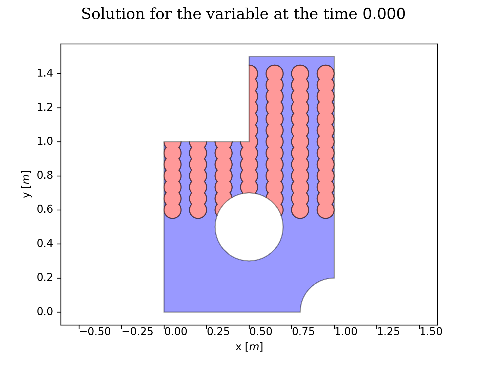
More simply, one can also split the domain by a single line. Note that the line should cut the domain through, otherwise the code will automatically crash. Defining a custom line as in the left figure, one has to give the first tuple value (integer) depending on the part of the cutting domain he likes to consider (see the technical documentation for more details). Automatic cutting lines are also predefined, as shown in the right figure. Bezier cuts are defined in a similar spirit, though one has to pay attention to the definition of the drag vector (see the technical documentation).
Cut through predefined lines
patch = [(2,0.6,1.5,0,0.5)]
SD.GetSubdomains(patch, Mesh)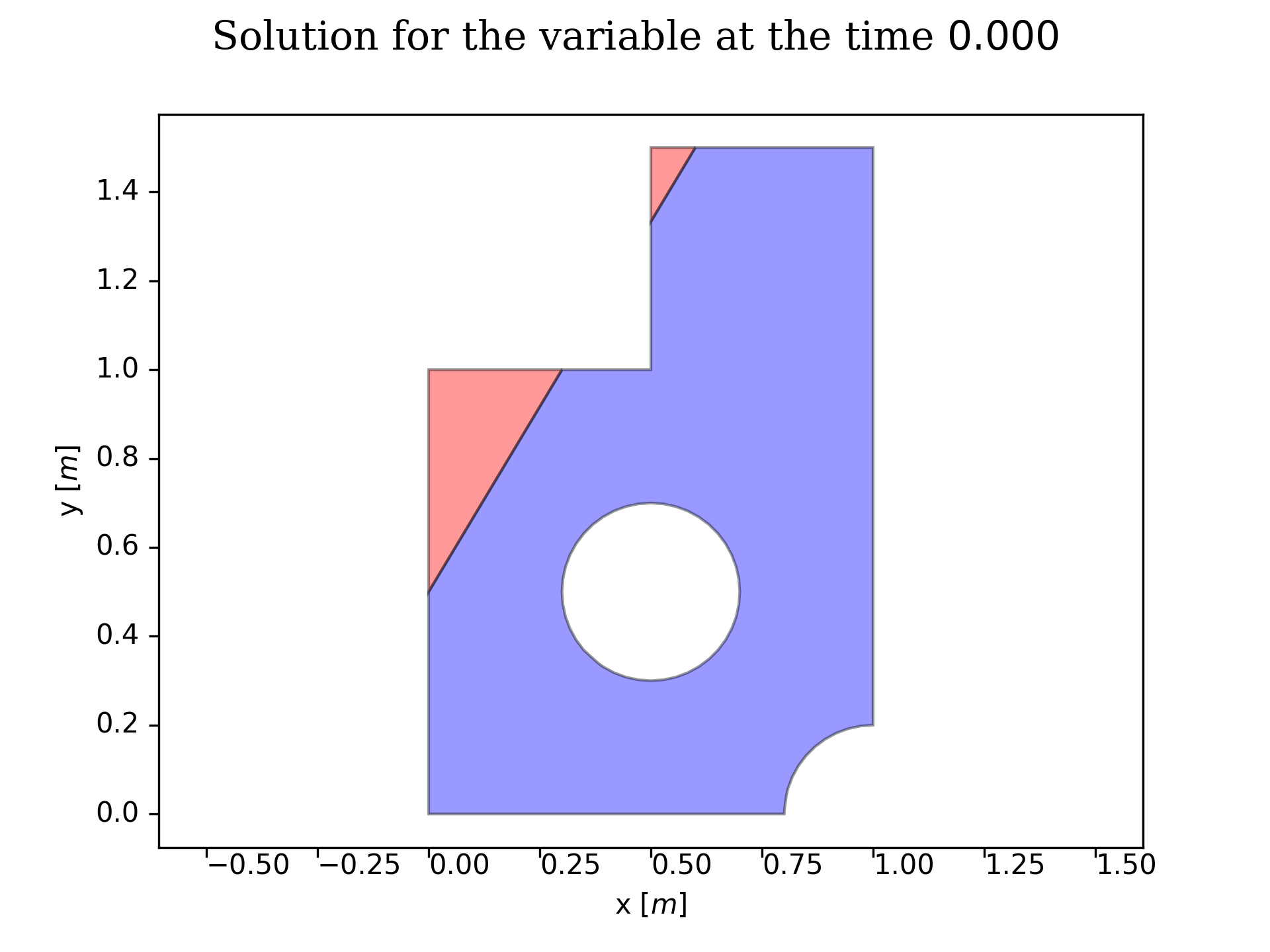
Cut through custom lines
patch = [1]
SD.GetSubdomains(patch, Mesh)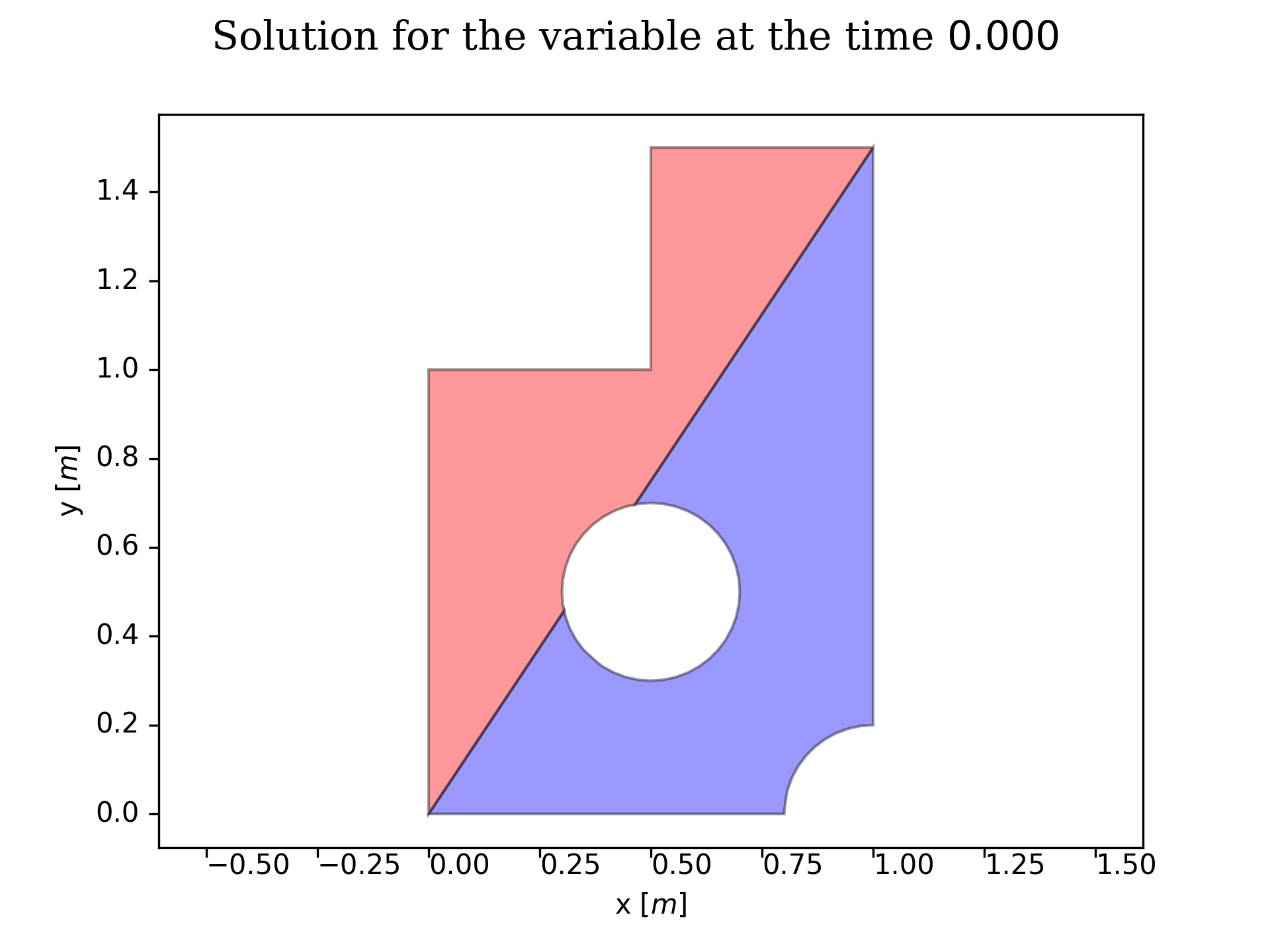
Cut through bezier lines (1)
patch = [(0, 0,2, 0.5, 0.2, -0.5, -0.2)]
SD.GetSubdomains(patch, Mesh)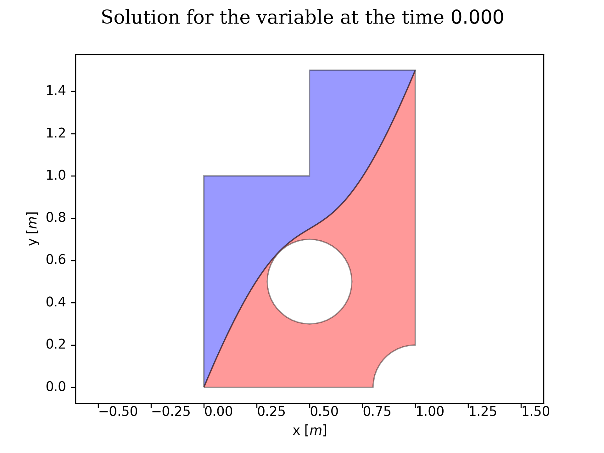
Cut through bezier lines (2)
patch = [(0, 0,1, 0.5, 0.2, -0.5, 0.2)]
SD.GetSubdomains(patch, Mesh)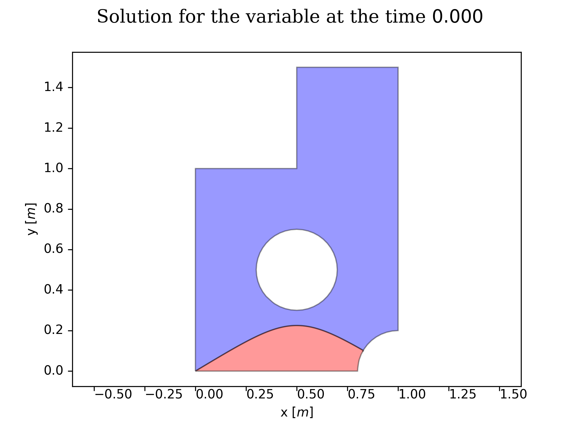
Lastly, one can also define directly the patch as a polygonal shape given by its vertices. There too, holes and boundaries are not imparing the patch’s definition.
Patches may follow boundaries
patch = [[[0.5, 0],[0.5, 0.5],[0, 0.5]]]
SD.GetSubdomains(patch, Mesh)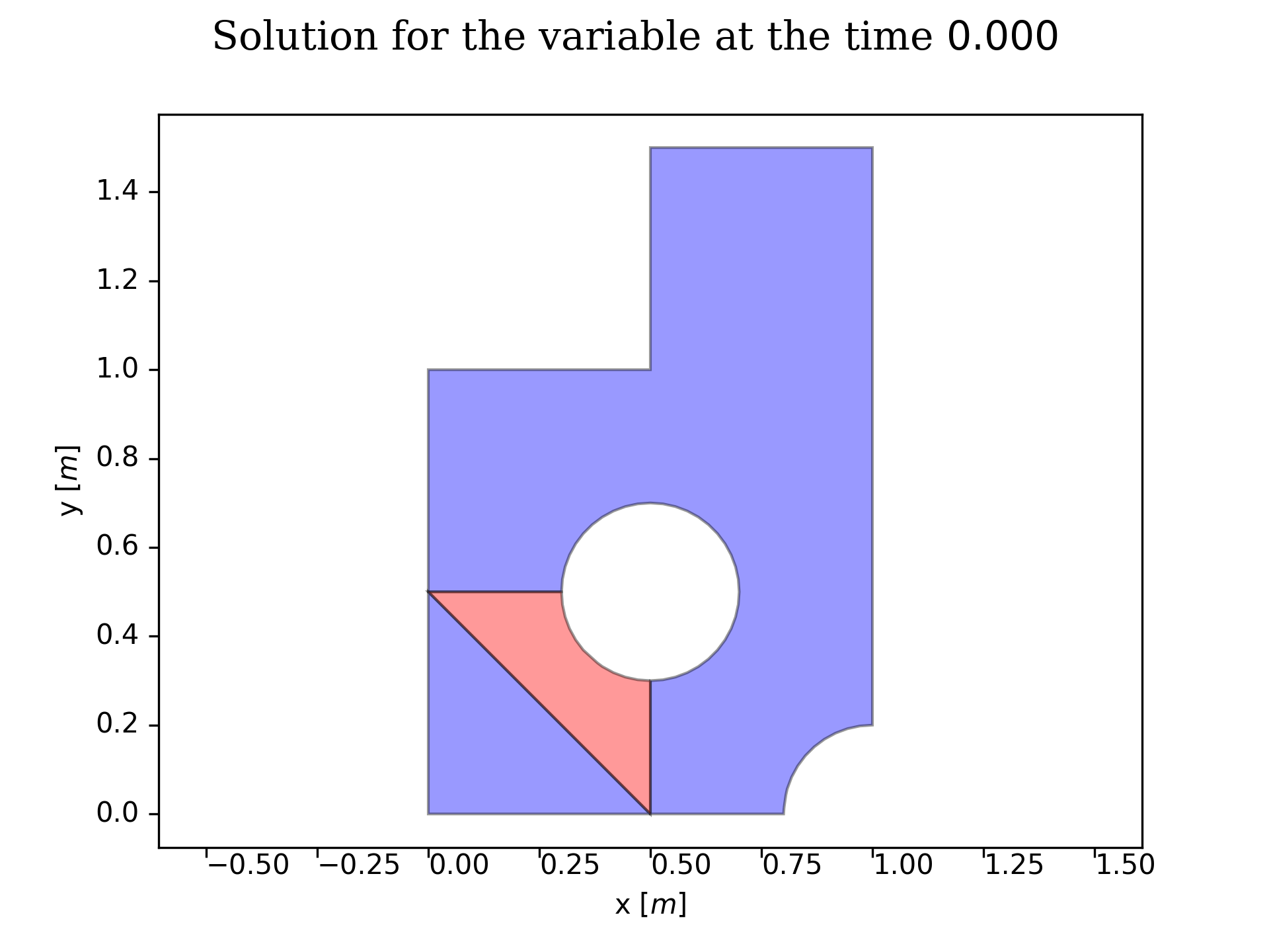
Patches may be defined over holes
patch = [[[0.2, 0.2],[0.8, 0.2],[0.5, 0.9],[0.3,0.7]]]
SD.GetSubdomains(patch, Mesh)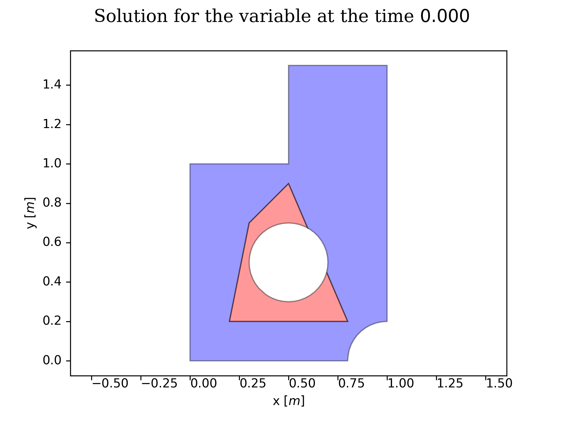
Case of several fluids
Let us now emphasise the definition of more than three subdomains. As shortly explained above in the “Generic principle” section, the subdomains have to be seen as a collection of superposing patches, from the right to the left of the given list. Below shows the patching of the subdomains giving the patches ordering. The color of the fluids according to their given order in the problem’s definition is [“blue”, “red”, “green”], and the patches are given accordingly to [“patch fluid red”, “patch fluid green”], the rightest given fluid beeing on the top of the superposition. The “patch fluid blue” is defined as the remaining non-assigned area within the computational domain.
Patches with the custom triangle on the top of the diagonal domain split
patch = [0, [[0.2, 0.2],[0.8, 0.2],[0.5, 0.9]]]
SD.GetSubdomains(patch, Mesh)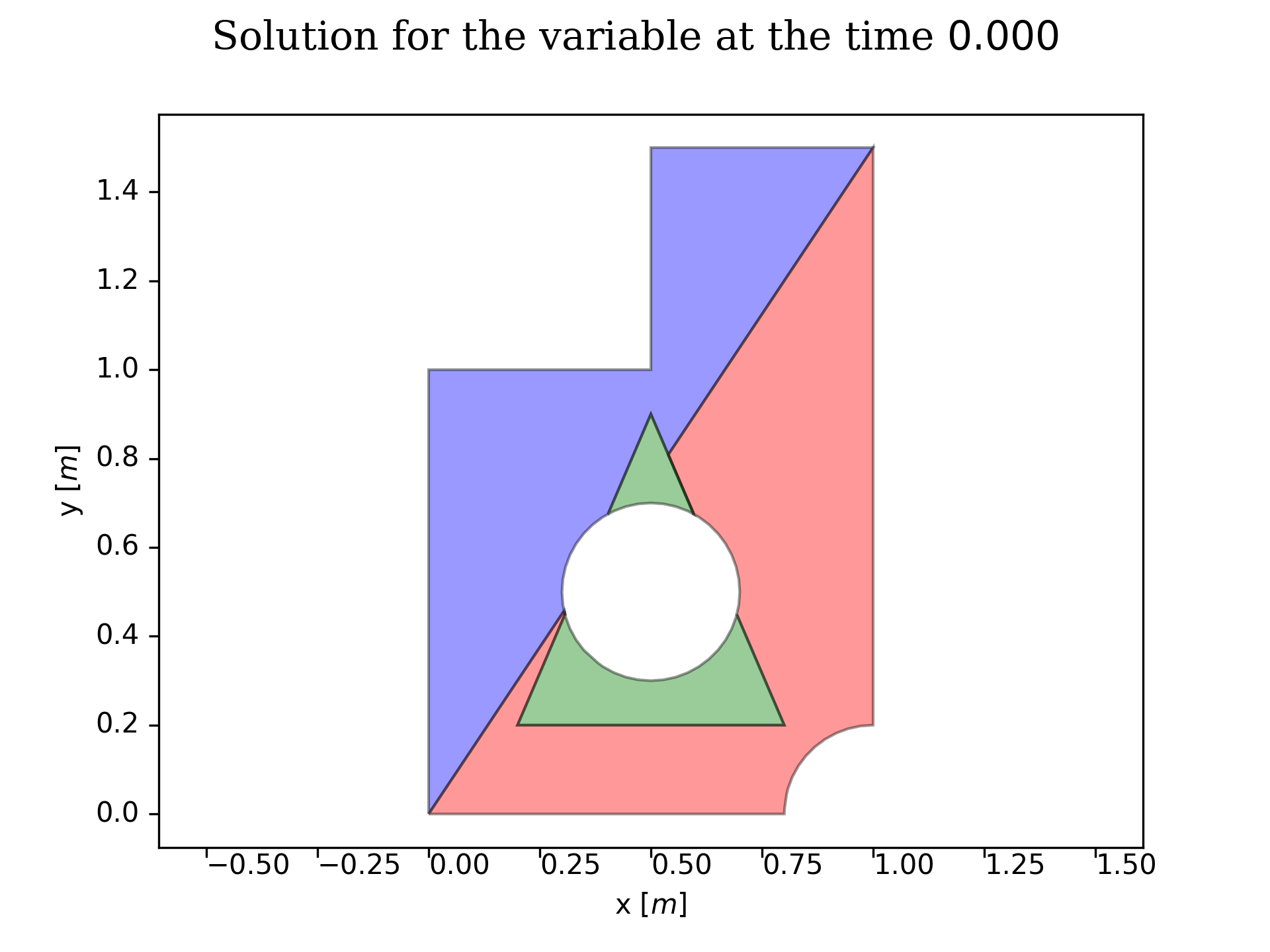
Patches with the diagonal domain split on the top of the custom triangle
patch = [[[0.2, 0.2],[0.8, 0.2],[0.5, 0.9]], 0]
SD.GetSubdomains(patch, Mesh)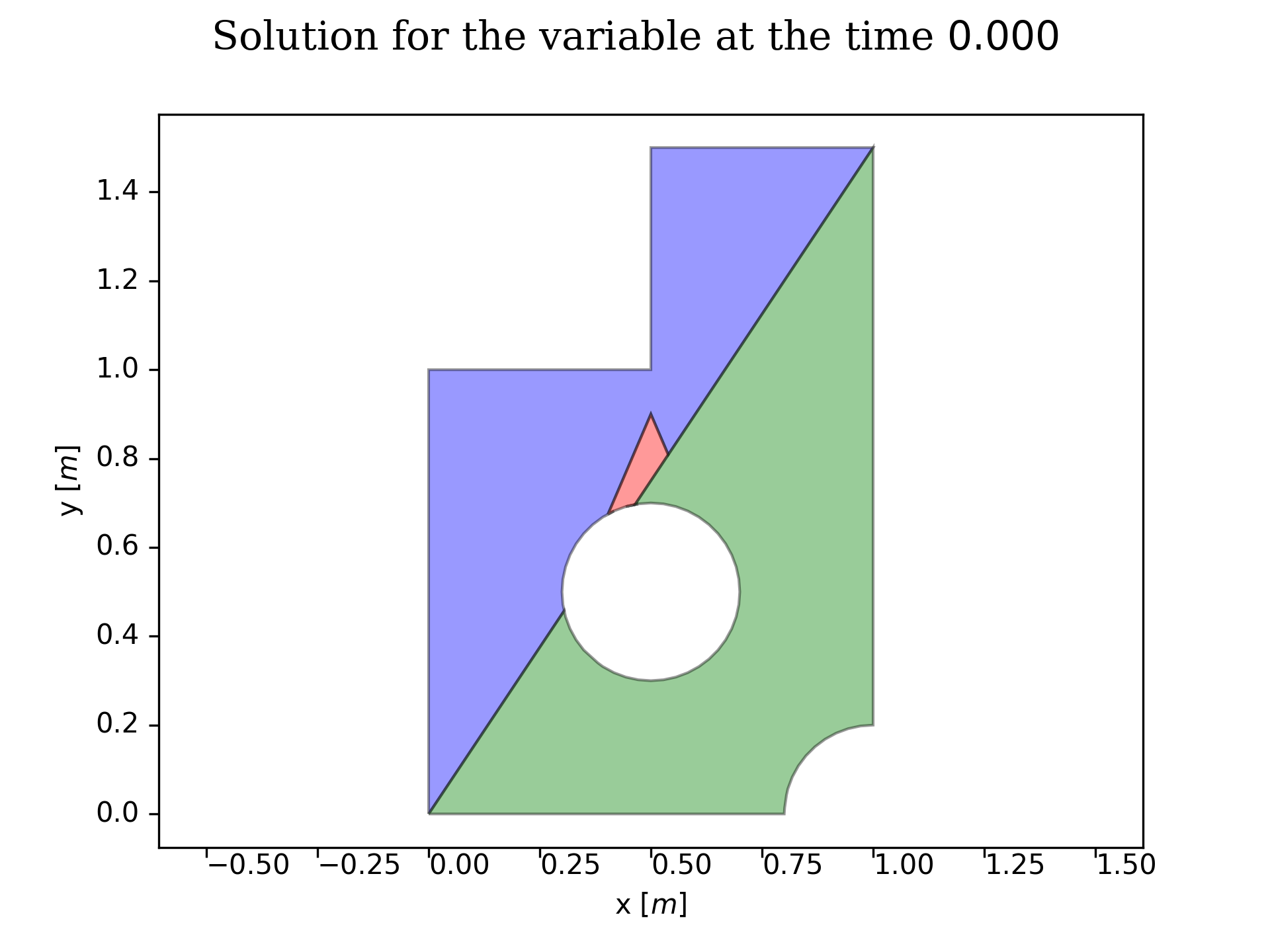
Routines taking care of the domain splitting and the subdomains definition
-
3_LESARD.SourceCode.ProblemDefinition.FluidSubdomains.GetSubdomains(SubDomainList, Mesh)¶ Patching the partial subdomains in order to define the actual fluid’s subdomains.
- Parameters
SubDomainList (shapely multipolygons list) – the list of all partial subdomains correspoding to the split given for each fluid (NbFluids-1)
Mesh (MeshStructure) – the mesh associated to the problem and subdomains
- Returns
the list of the proper fluid’s subdomains
- Return type
Polys (shapely multipolygons list)
Principle
The subdomains are defined as a patchwork. The domains given in the SubDomainList are superposed from left to right in the order of the list (the domain at the most right is on the top of all the others, the one on the most left is at the bottom of all the others).
Assuming N fluids, the fluid N will be located on the whole patch given at the last position of the SubDomainList the fluid N-1 will be located on the whole patch given at the one to last position of the SubDomainList, minus the patch of the fluid N the fluid 1 will be located on the patch consisting of the Domain minus all the other patches.
Note
This routine supports non arc-connected domains but not disconnected domains
-
3_LESARD.SourceCode.ProblemDefinition.FluidSubdomains.Mapper(Id, Mesh)¶ Mapper routine for the subdomain’s partial patches definition that are defined in the below functions.
Parameters
Mesh (MeshStructure) – the mesh associated to the problem and subdomains
Id (integer, tuple or list) – the index and properties corresponding to the type of simple patches one desires, considering the smaller rectangle containing the outer domain as the reference shape. The subdomain’s definition reads then as follows upon the type of the given argument.
- integer (predefined simple patch creation)
- Domain split by diagonal bottom left to upper right, right part
- Domain split by diagonal bottom left to upper right, left part
- Domain split by diagonal bottom right to upper left, right part
- Domain split by diagonal bottom right to upper left, left part
- Domain split by halfplane vertical line, right part
- Domain split by halfplane vertical line, left part
- Domain split by halfplane horizotal line, bottom part
- Domain split by halfplane horizotal line, top part
- tuple (index and information specifying the nature and properties of the whished partial patches):
- Domain split through a bezier spline, right or bottom partId = (0, VertexId1, VertexId2, DragVector1X, DragVector1Y, DragVector2X, DragVector2Y)
- Domain split through a bezier spline, left or top partId = (1, VertexId1, VertexId2, DragVector1X, DragVector1Y, DragVector2X, DragVector2Y)
- Domain split through a line given by two vertices, right or bottom partId = (2, Vertex1X, Vertex1Y, Vertex2X, Vertex2Y)
- Domain split through a line given by two vertices, left or top partId = (3, Vertex1X, Vertex1Y, Vertex2X, Vertex2Y)
- Dropplets in a boxId = (4, BoxCenterX, BoxCenterY, BoxWidthX, BoxWidthY, BubblesDiameter, BubblesSpacingX, BubblesSpacingY)
list: the list of vertices forming the polygonal patch
- Returns
the Patch forming the considered subdomain
- Return type
Patch (shapely multipolygon)
Note
The code aborts upon a wrong shape of Id; it does not check the validity of the input. Code failure without clear explanation may raise in case of misuse.
Routines that are practically splitting the given plane
-
3_LESARD.SourceCode.ProblemDefinition.FluidSubdomains.DroppletsInBox(Mesh, BoxCenter, BoxWidth, BubblesProp)¶ Creates a patch consisting of bubbles in a box.
- Parameters
Mesh (MeshStructure) – the mesh associated to the problem and subdomains
BoxCenter (float list-alike) – the x and y coordinates of the box center
BoxWidth (float list-alike) – the x and y width of the box
BubblesProp (float list-alike) – the dropplets diameter, their x spacing and their y spacing
- Returns
the corresponding partial patch
- Return type
polygon (shapely mutlipolygon)
Note
If there the bubbles are too large w.r.t. their spacing, they will be merged and form “8”-like shapes.
-
3_LESARD.SourceCode.ProblemDefinition.FluidSubdomains.CutThroughBezierLine(Part, Id, Mesh)¶ Creates a patch consisting of the desired part of a plane after being cut through a Bezier line.
Parameters
Mesh (MeshStructure) – the mesh associated to the problem and subdomains
Part (integer) – the part of the plane to conserve (0 for right or bottom, 1 for top or left)
Id (float list-alike) – list giving the parameters of the bezier curve as follows
- Id[0:2]: vertex Id of the outer polygon on which will be stitched the bezier line(that can be converted to integers, corresponding to 4 (number of boxing corners) + IndexOfOuterPolygonVertex ).It can also be the boundig box corners (WishedCornerId),there, WishedCornerId has to be given according to the order: [BottomLeft, BottomRight, TopRight, TopLeft])
- Id[2:4]: Vector giving the direction and strenght for which to drag the curve from the 1st given vertex(will be pondered by the X-Y lengths of the polygon’s bounding box)
- Id[4:6]: Vector giving the direction and strenght for which to drag the curve from the 2nd given vertex(will be pondered by the X-Y lengths of the polygon’s bounding box)
- Returns
the corresponding partial patch
- Return type
polygon (shapely mutlipolygon)
Note
The resolution of the spline is set to be 20times the mesh size
-
3_LESARD.SourceCode.ProblemDefinition.FluidSubdomains.CutThroughAbsoluteLine(Part, Line, Mesh)¶ Creates a patch consisting of the desired part of a plane after being cut through an absolute line.
- Parameters
Mesh (MeshStructure) – the mesh associated to the problem and subdomains
Part (integer) – the part of the plane to conserve (0 for right or bottom, 1 for top or left)
Line (float numpy array) – list of the x-y coordinates of points defining the line (nbpoints x 2) the extremities of the line should be outside or on the boundary of the outer polygon
- Returns
the corresponding partial patch
- Return type
polygon (shapely mutlipolygon)
-
3_LESARD.SourceCode.ProblemDefinition.FluidSubdomains.CutThroughRelativeLine(Part, Line, Mesh)¶ Creates a patch consisting of the desired part of a plane after being cut through an absolute line.
- Parameters
Mesh (MeshStructure) – the mesh associated to the problem and subdomains
Part (integer) – the part of the plane to conserve (0 for right or bottom, 1 for top or left)
Line (lambda function) – given the bounding box points, creates the list of shapely points to consider
- Returns
the corresponding partial patch
- Return type
polygon (shapely mutlipolygon)
Note
If there the bubbles are too large w.r.t. their spacing, they will be merged and form “8”-like shapes.
The resolution of the spline is set to be 20times the mesh size
Routines that perform post-fluid subdomain definition tasks
-
3_LESARD.SourceCode.ProblemDefinition.FluidSubdomains.ExportFluidFlags(SubDomains, Mesh)¶ Taggs the Dofs according to the fluid index active at its location.
- Parameters
SubDomains (shapely multipolygons list) – the list of all subdomains correspoding to each given fluid
Mesh (MeshStructure) – the mesh associated to the problem, where the subdomains have to be defined
- Returns
list of the Flags selecting the proper fluid (NbDofs)
- Return type
Flags (numpy integer array)
Note
In case of an element on the interface, the first registered fluid prevails in the tag
The flags are initialised to -1: if there is a -1 in the output Flag list, the subdomains definition failed